Home

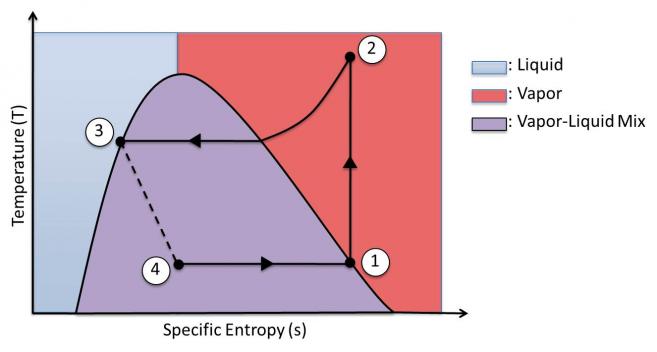
magnético Conversa Convite ts diagram for a vapor compression refrigeration system Dedicar virtude Medicina forense

What is the T-s diagram for the Carnot refrigeration cycle? - Quora

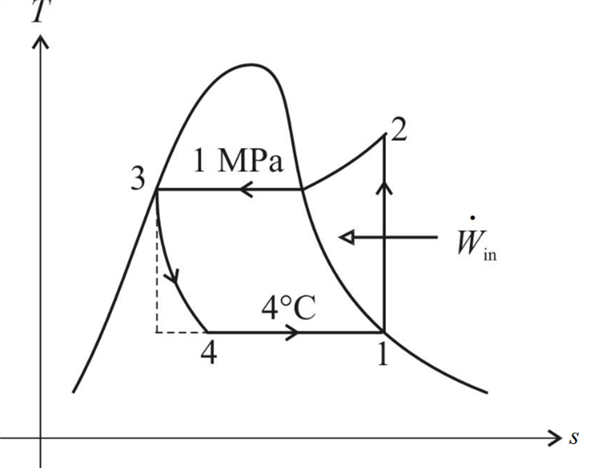
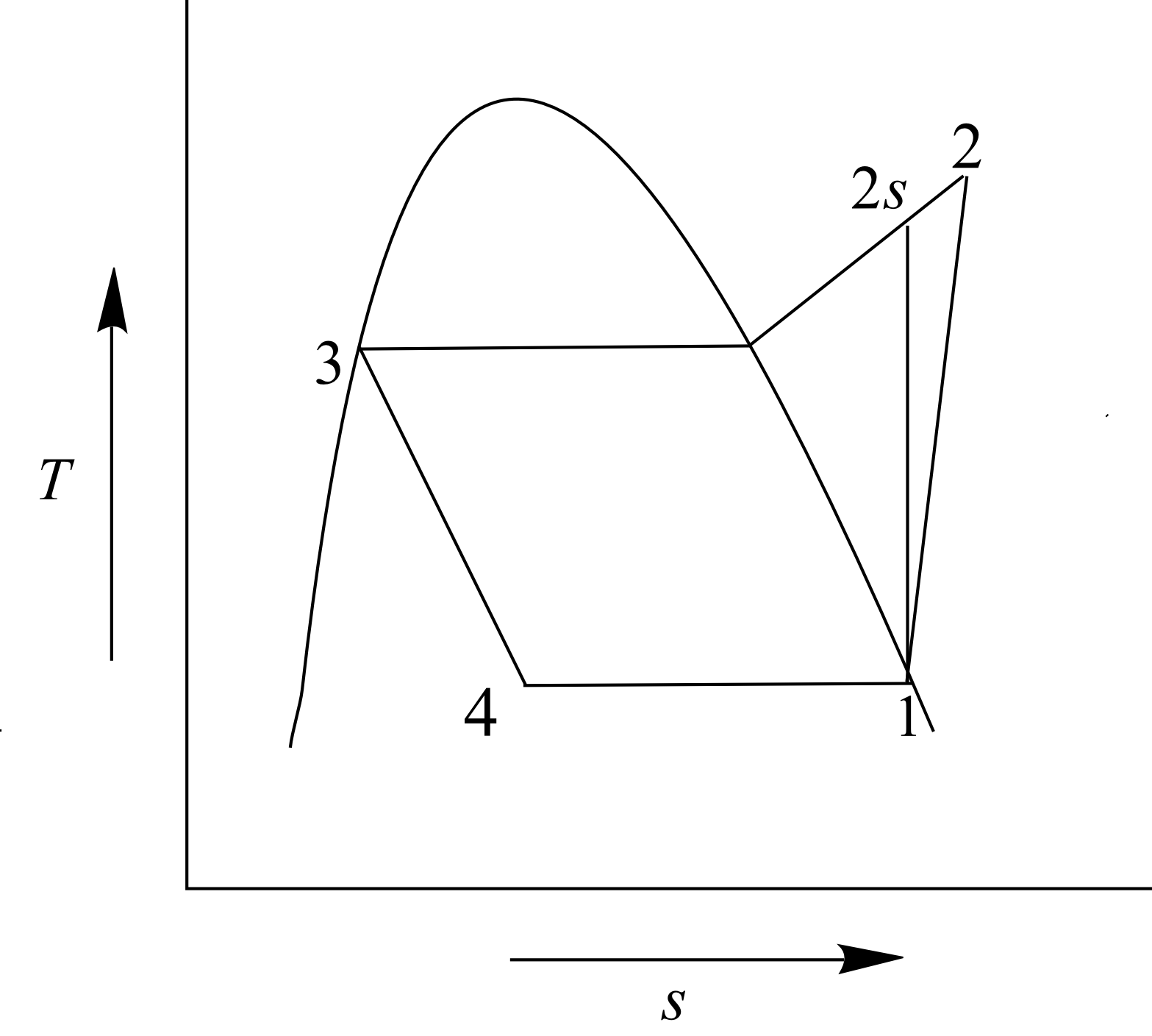
Solved: Chapter 10 Problem 27P Solution | Fundamentals Of Engineering  Thermodynamics 8th Edition | Chegg.com
Solved: Chapter 10 Problem 27P Solution | Fundamentals Of Engineering Thermodynamics 8th Edition | Chegg.com
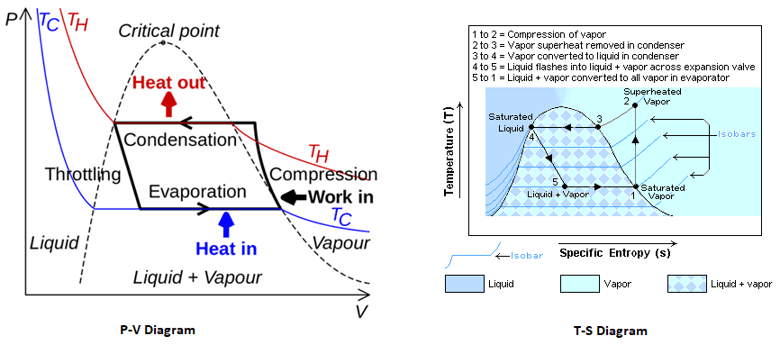
4. T-s diagram for Actual Vapor Compression Refrigeration Cycle (4) |  Download Scientific Diagram
4. T-s diagram for Actual Vapor Compression Refrigeration Cycle (4) | Download Scientific Diagram

Energy and Exergy Analysis of Refrigeration Systems | IntechOpen

Ch10, Lesson C, Page 6 - Increased COP: Multistage V-C Refrigeration Cycle

Engineering 41 Laboratory 6

Vapor-Compression Refrigeration

5. Vapour Compression Cycle On Ph And T S Diagrams. - Lessons - Blendspace

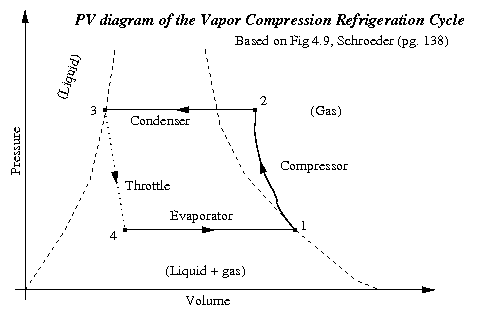
Mechanism And Working Of A Vapour Compression Refrigeration System - With PV  And TS Diagram | Mecholic
Mechanism And Working Of A Vapour Compression Refrigeration System - With PV And TS Diagram | Mecholic
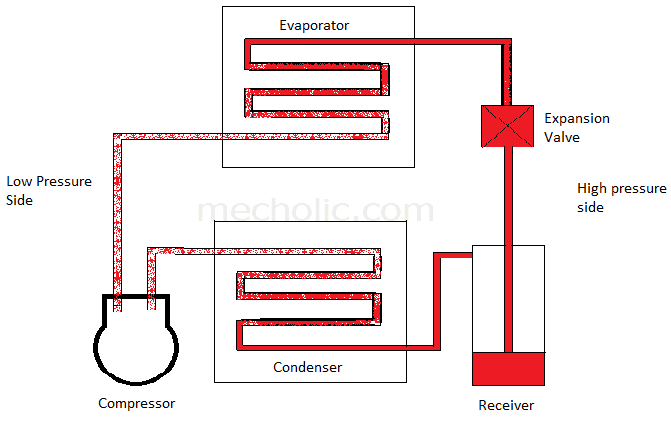
Mechanism And Working Of A Vapour Compression Refrigeration System - With PV  And TS Diagram | Mecholic
Mechanism And Working Of A Vapour Compression Refrigeration System - With PV And TS Diagram | Mecholic

T-S diagram of simple vapour compression refrigeration system | Download  Scientific Diagram
T-S diagram of simple vapour compression refrigeration system | Download Scientific Diagram

Refrigeration Cycles Real Vapor Compression Cycle | PDF |  Chlorofluorocarbon | Refrigeration
Refrigeration Cycles Real Vapor Compression Cycle | PDF | Chlorofluorocarbon | Refrigeration

Design of Vapor-Compression Refrigeration Cycles

Thermodynamic Calculations of Two-Stage Vapor Compression Refrigeration  Cycle with Flash Chamber and Separate Vapor Mixing Intercooler -  Application Center
Thermodynamic Calculations of Two-Stage Vapor Compression Refrigeration Cycle with Flash Chamber and Separate Vapor Mixing Intercooler - Application Center

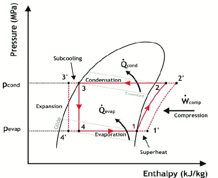
Draw P-H and T-S diagram when the vapours are superheated at the end of  compression and with under cooling of liquid
Draw P-H and T-S diagram when the vapours are superheated at the end of compression and with under cooling of liquid

Vapor-compression refrigeration - Wikipedia

ISAT Module III: Building Energy Efficiency - ppt video online download

6 a b c, Schematic and T-s diagram for the ideal vapor-compression... |  Download Scientific Diagram
6 a b c, Schematic and T-s diagram for the ideal vapor-compression... | Download Scientific Diagram

CU Faculty
CU Faculty

Solved: An ideal vapor-compression refrigeration cycle that uses r... |  Chegg.com
Solved: An ideal vapor-compression refrigeration cycle that uses r... | Chegg.com

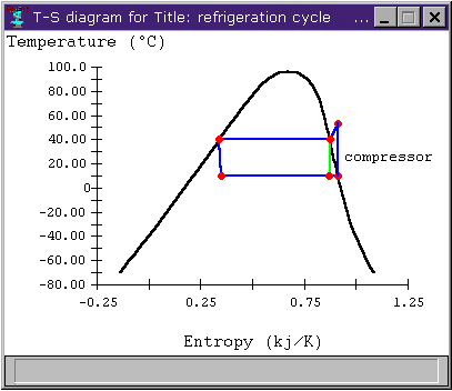
T-s diagram of the vapour-compression refrigeration cycle considered in...  | Download Scientific Diagram
T-s diagram of the vapour-compression refrigeration cycle considered in... | Download Scientific Diagram
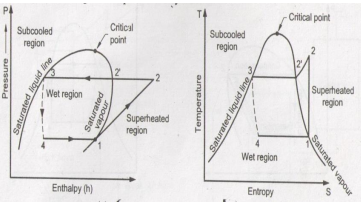
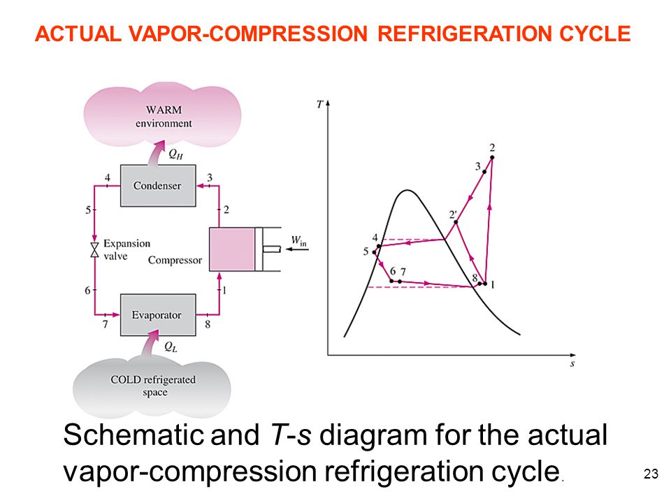
Comparison of Actual and Theoretical Vapor Compression Cycle

Comparison of Actual and Theoretical Vapor Compression Cycle

Explain vapour compression refrigeration cycle on T-S and p-h charts.. |  Topicwise paper solutions for MSBTE
Explain vapour compression refrigeration cycle on T-S and p-h charts.. | Topicwise paper solutions for MSBTE

A vapor compression refrigeration system circulates refrigerant 134a at a  rate of 6kg/min. The refrigerant enters the compressor at -10 o C, 1.4 bar,  and exits at 7 bar. The isentropic compressor
A vapor compression refrigeration system circulates refrigerant 134a at a rate of 6kg/min. The refrigerant enters the compressor at -10 o C, 1.4 bar, and exits at 7 bar. The isentropic compressor

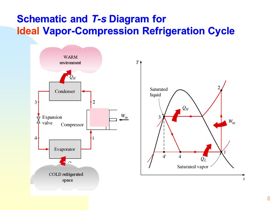
Schmatic and T-s Diagram for Ideal Vapor-Compression Refrigeration Cycle

A vapor compression cycle presentation on a Ts-diagram. | Download  Scientific Diagram
A vapor compression cycle presentation on a Ts-diagram. | Download Scientific Diagram

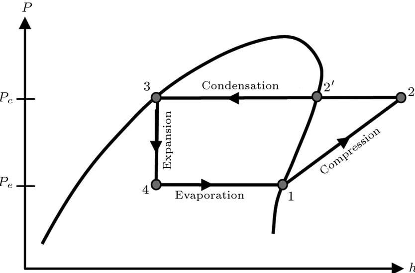
B) Draw T-S, P-H diagrams of vapour compression refrigeration system. -  HomeworkLib
B) Draw T-S, P-H diagrams of vapour compression refrigeration system. - HomeworkLib